
Precision is the foundation of every successful CNC machining project. A part may have the correct dimensions on paper, but it can still fail during assembly if its features are not aligned, oriented, or positioned correctly. This is where GD&T in CNC machining becomes essential. It provides a standardized way to define the allowable variation of every critical feature, helping designers, machinists, and quality inspectors work with the same expectations.
Instead of relying only on linear dimensions and plus/minus tolerances, GD&T uses internationally recognized symbols to communicate design intent. This reduces confusion, improves consistency, and makes precision manufacturing more reliable. Whether the component is used in automotive, aerospace, medical, or industrial machinery, proper application of GD&T helps ensure that every machined part performs as intended.
This guide explains the fundamentals of GD&T in CNC machining, its core principles, and how it supports accurate machining, inspection, and assembly in modern manufacturing.
What is GD&T in CNC Machining?
GD&T stands for Geometric Dimensioning and Tolerancing. It is a symbolic engineering language used on technical drawings to define the acceptable variation in the geometry of manufactured parts.
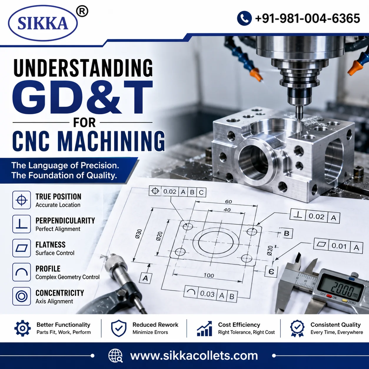
Unlike conventional dimensioning, GD&T focuses on how a part should function rather than simply specifying its size. It controls the form, orientation, profile, location, and runout of features so that every component fits and operates correctly in the final assembly.
In GD&T in CNC machining, these symbols help programmers create accurate toolpaths, assist machinists during setup, and allow inspectors to verify the finished component against clearly defined requirements.
Why Standard Dimensions Are Not Always Enough?
Imagine a mounting plate with four bolt holes. Each hole may meet its diameter tolerance, but if their positions vary slightly, the bolts may not fit during assembly.
Traditional dimensions cannot always define these relationships clearly. GD&T eliminates this uncertainty by controlling the exact location, orientation, and allowable variation of every important feature.
This reduces production errors and improves interchangeability between parts manufactured on different machines or at different production facilities.
GD&T in CNC Machining
Modern CNC machines can produce highly accurate components. However, machining accuracy depends on more than machine capability. The manufacturing team also needs clear engineering instructions.
That is exactly what GD&T in CNC machining provides.
It helps manufacturers:
- Reduce ambiguity in engineering drawings.
- Improve communication between design and production teams.
- Maintain consistent part quality.
- Reduce scrap and rework.
- Simplify quality inspection.
- Improve assembly accuracy.
- Optimize manufacturing costs without compromising function.
Instead of applying unnecessarily tight tolerances everywhere, engineers can control only the features that directly affect performance. This approach makes machining more practical and cost-effective.
Traditional Dimensioning vs GD&T
| Traditional Dimensioning | GD&T |
|---|---|
| Focuses mainly on size. | Defines both size and geometric relationships. |
| Can lead to multiple interpretations. | Uses standardized engineering symbols. |
| Often requires tighter overall tolerances. | Controls only functional features. |
| Inspection methods may vary. | Provides consistent inspection criteria. |
| Suitable for simple components. | Ideal for precision CNC machining and assemblies. |
For precision machining, GD&T offers greater clarity and better manufacturing efficiency than conventional dimensioning alone.
Core Concepts of GD&T in CNC Machining
Understanding a few basic concepts makes it much easier to read engineering drawings and apply GD&T correctly during CNC machining.
1. Datums
A datum is a theoretical reference used to locate and measure all other features on a component.
Think of a datum as the starting point for every important measurement. During machining, fixtures and workholding systems are often designed around these reference surfaces.
Most precision components use three primary datums.
- Primary Datum
- Secondary Datum
- Tertiary Datum
These references establish a stable coordinate system for machining and inspection.
When reliable workholding is required, selecting the correct CNC collet chuck helps maintain consistent positioning throughout the machining process.
2. Feature Control Frame (FCF)
The Feature Control Frame is one of the most important elements in GD&T.
It contains all the information needed to control a specific feature.
A typical Feature Control Frame includes:
- GD&T symbol
- Tolerance value
- Tolerance modifier (when required)
- Referenced datums
Instead of lengthy engineering notes, a Feature Control Frame communicates manufacturing requirements quickly and consistently.
3. Tolerance Zones
Every geometric tolerance defines an allowable tolerance zone.
Rather than specifying one exact location, GD&T allows a controlled area where a feature may exist while still functioning correctly.
Depending on the symbol used, tolerance zones may be:
- Cylindrical
- Rectangular
- Circular
- Parallel
- Angular
These controlled zones help CNC programmers maintain functional accuracy without creating unnecessarily difficult machining operations.
How GD&T Improves CNC Machining Accuracy?
Every stage of manufacturing benefits from properly applied GD&T.
Design Stage
Engineers communicate the functional intent of each feature instead of relying only on dimensions.
Programming Stage
CNC programmers understand which features require tighter control and which allow normal machining variation.
Machining Stage
Operators can plan better setups, select suitable cutting strategies, and minimize unnecessary adjustments.
Inspection Stage
Quality inspectors evaluate components against clearly defined acceptance criteria instead of subjective interpretation.
This workflow reduces production delays and improves repeatability across production batches.
Common GD&T Symbols Used in CNC Machining
Although GD&T contains several symbols, only a few appear frequently in precision machining applications.
| Control | Purpose | Typical CNC Application |
|---|---|---|
| Straightness | Controls line accuracy | Guide rails and shafts |
| Flatness | Controls surface flatness | Machine bases and mounting plates |
| Perpendicularity | Maintains 90° alignment | Fixture surfaces and drilled holes |
| Parallelism | Keeps surfaces parallel | Sliding machine components |
| True Position | Defines feature location | Bolt circles and hole patterns |
| Profile | Controls complex geometry | Aerospace and mould components |
Each symbol controls a different aspect of part geometry. Selecting the correct control depends on the function of the component rather than its appearance alone.
The accuracy achieved through GD&T also depends on reliable tool holding. Choosing the right ER collet system helps reduce runout and supports repeatable machining performance during high-precision operations.
Major GD&T Symbol Categories Explained
Every GD&T symbol controls a specific geometric characteristic of a part. Understanding these categories helps designers create functional drawings and allows machinists to interpret them correctly during CNC machining.
1. Form Controls
Form controls regulate the shape of individual features. They do not require datum references because they evaluate the feature itself.
| GD&T Control | Purpose | Typical CNC Application |
|---|---|---|
| Straightness | Controls the straightness of a line or axis. | Precision shafts and guide rods. |
| Flatness | Ensures a surface remains flat. | Machine bases and fixture plates. |
| Circularity | Maintains a perfect circular profile. | Turned cylindrical components. |
| Cylindricity | Controls the complete cylindrical surface. | Bearing journals and precision sleeves. |
2. Orientation Controls
Orientation controls define how one feature is positioned relative to another reference surface.
| Control | Purpose | Application |
|---|---|---|
| Parallelism | Keeps two surfaces parallel. | Sliding machine components. |
| Perpendicularity | Maintains a true 90° relationship. | Drilled holes and fixture faces. |
| Angularity | Maintains a specified angle. | Custom fixtures and angled features. |
3. Location Controls
Location controls determine where a feature should exist in relation to the selected datums.
| Control | Purpose | Application |
|---|---|---|
| True Position | Controls feature location. | Bolt circles and mounting holes. |
| Concentricity | Aligns feature centers. | Rotating shafts. |
| Symmetry | Maintains balanced geometry. | Mirror-machined components. |
4. Profile Controls
Profile tolerances define the acceptable variation of complex curves and surfaces. They are widely used in aerospace, medical, mould, and automotive machining.
- Profile of a Line
- Profile of a Surface
5. Runout Controls
Runout controls are critical for rotating components. They help minimize vibration and improve rotational accuracy.
- Circular Runout
- Total Runout
How to Read a GD&T Drawing?
Many machining errors occur because the drawing is interpreted incorrectly. Following a simple sequence makes the process much easier.
Step 1 – Identify the Datums
Locate the primary, secondary, and tertiary datums first. These establish the coordinate system for machining and inspection.
Step 2 – Read the Feature Control Frame
Identify the GD&T symbol, tolerance value, modifiers, and referenced datums.
Step 3 – Understand the Controlled Feature
Determine which surface, hole, slot, or axis the tolerance applies to.
Step 4 – Review Size Dimensions
Confirm that dimensional tolerances and geometric tolerances work together without conflict.
Step 5 – Plan Inspection
Decide which inspection equipment will verify the feature accurately.
Following this sequence reduces setup errors and improves machining consistency.
MMC, LMC and RFS Explained
These modifiers make GD&T more practical by allowing controlled variation while maintaining functional performance.
Maximum Material Condition (MMC)
MMC represents the condition where a feature contains the maximum amount of material.
For example, the largest shaft diameter or the smallest hole diameter represents MMC.
Using MMC often provides additional manufacturing flexibility while maintaining assembly requirements.
Least Material Condition (LMC)
LMC represents the condition containing the least amount of material.
For example, the smallest shaft or the largest hole.
Regardless of Feature Size (RFS)
When no modifier is specified, the geometric tolerance applies regardless of the feature size.
Understanding these modifiers helps CNC programmers produce functional parts without unnecessary machining restrictions.
Practical Examples of GD&T in CNC Machining
Precision Shaft Manufacturing
A shaft used with rolling bearings requires excellent concentricity and low runout. Even a small deviation can create vibration and premature bearing wear.
Accurate workholding and properly maintained ER Collets help maintain consistent concentricity during turning operations.
Fixture Plates
Bolt holes must follow true position tolerances. Even correctly sized holes may fail during assembly if their locations are inaccurate.
Machine Spindles
Flatness and perpendicularity ensure stable mounting surfaces and improve machining accuracy.
Hydraulic Manifolds
Port locations require accurate positioning to ensure leak-free assembly and proper fluid flow.
Mould Components
Surface profile tolerances help maintain complex cavity shapes and improve product quality.
Inspection Methods Used for GD&T
Inspection is an essential part of applying GD&T in CNC machining. Selecting the correct inspection method depends on the feature being evaluated.
| Inspection Tool | Typical Use |
|---|---|
| Vernier Caliper | General dimensional checks. |
| Micrometer | High-accuracy diameter measurement. |
| Dial Indicator | Runout and alignment checks. |
| Height Gauge | Datum-based measurements. |
| Coordinate Measuring Machine (CMM) | Complex GD&T inspection. |
| Optical Measuring System | Small precision features. |
For production environments requiring tight tolerances, CMM inspection provides repeatable and reliable measurement results.
Common GD&T Mistakes to Avoid
Applying Tight Tolerances Everywhere
Every feature does not require extremely tight tolerances. Over-tolerancing increases machining time, inspection effort, and manufacturing cost.
Choosing Incorrect Datums
Poor datum selection creates inconsistent setups and inaccurate measurements.
Ignoring Functional Requirements
GD&T should always support the way the component functions inside the final assembly.
Misreading Feature Control Frames
Skipping modifiers or datum references often leads to machining errors.
Using Poor Tool Holding
Even a perfect drawing cannot compensate for unstable tool holding. Selecting the correct tool holder and maintaining proper clamping improves machining stability and dimensional accuracy.
Best Practices for Applying GD&T in CNC Machining
- Define datums based on actual functional surfaces.
- Apply geometric tolerances only where required.
- Select practical tolerance values.
- Use consistent inspection methods.
- Verify machining capability before finalizing tolerances.
- Choose high-quality workholding components for repeatable accuracy.
- Inspect first-off components before full production.
- Maintain collets and holders to reduce runout.
Reliable workholding directly supports successful GD&T implementation. Understanding how collet selection affects surface finish and tolerance can help improve machining consistency across production batches.
How Quality Tool Holding Supports GD&T Accuracy?
Applying GD&T correctly is only one part of precision machining. The machine setup, tooling, and workholding system must also support the required tolerances. Even a well-designed drawing can produce inaccurate parts if the tooling introduces excessive runout or vibration.
High-quality collets, collet chucks, and tool holders help maintain repeatable positioning throughout the machining cycle. Stable tool holding improves dimensional accuracy, surface finish, and overall process reliability.
Choosing the correct workholding solution depends on the machining operation, workpiece material, spindle speed, and required tolerance. Understanding the differences between various collets and tool holders helps manufacturers select the most suitable option for each application.
Regular inspection of collets is equally important. Worn or damaged collets can increase runout, reduce gripping force, and affect the geometric accuracy required by GD&T-controlled features.
Industries That Depend on GD&T in CNC Machining
Many industries rely on GD&T because their components require consistent quality and precise assembly.
- Automotive manufacturing
- Aerospace components
- Medical devices
- Industrial automation
- Hydraulic and pneumatic systems
- Oil and gas equipment
- Defence manufacturing
- Precision tooling
In these industries, proper application of GD&T in CNC machining helps reduce assembly issues, improve interchangeability, and maintain product quality across production batches.
Why Engineering Teams Should Understand GD&T?
GD&T is not only for design engineers. Every department involved in manufacturing benefits from understanding its principles.
- Design engineers communicate functional requirements clearly.
- CNC programmers develop efficient machining strategies.
- Machine operators perform more accurate setups.
- Quality inspectors verify parts using standardized criteria.
- Production managers reduce scrap and rework.
When every team member works from the same engineering language, production becomes more predictable and quality remains consistent.
About Sikka Sales Corporation
For precision machining applications, the quality of workholding components is just as important as the machining process itself. Sikka Sales Corporation has built its expertise around manufacturing precision collets designed for demanding industrial applications.
Sikka Precision Technologies is a professionally owned and operated company that manufactures precision collets using high-quality steel. Its product range is developed to support reliable gripping performance, dimensional consistency, and long service life across different machining environments.
The company manufactures solutions for various machining requirements, including ER Collets, DIN Collets, Traub Collets, 5C Collets, Collet Chucks, Feed Fingers, Expanding Collets, and other precision workholding accessories used in CNC machining.
Sikka Sales Corporation
31/3F, Street No. 1, Anand Parbat Industrial Area, New Delhi – 110005, India
Phone: +91-981-004-6365
Manufacturing professionals looking to locate the company can also refer to its Google Business Profile for business location details.
Frequently Asked Questions
What does GD&T stand for?
GD&T stands for Geometric Dimensioning and Tolerancing. It is a symbolic engineering system used to define the allowable geometric variation of manufactured parts.
Why is GD&T important in CNC machining?
It improves communication between designers, machinists, and inspectors. It also helps reduce manufacturing errors, improve assembly accuracy, and maintain consistent quality.
Is GD&T required for every CNC part?
No. Simple components may only require standard dimensions. GD&T becomes more valuable when parts must assemble accurately or perform under tight functional requirements.
What is the difference between true position and concentricity?
True position controls the allowable location of a feature relative to datums. Concentricity controls the alignment of feature axes around a common center.
Which inspection equipment is commonly used for GD&T?
Common inspection tools include vernier calipers, micrometers, dial indicators, height gauges, and Coordinate Measuring Machines (CMMs), depending on the required level of accuracy.
How do collets influence GD&T accuracy?
A quality collet provides stable gripping force and minimizes runout. This helps the machine maintain the dimensional and geometric tolerances specified on the engineering drawing.
Conclusion
Understanding GD&T in CNC machining is essential for producing parts that not only meet dimensional requirements but also function correctly during assembly. By defining the allowable variation of form, orientation, profile, and location, GD&T creates a common engineering language that improves communication throughout the manufacturing process.
Successful implementation depends on more than engineering drawings alone.
Accurate machine setup, reliable inspection methods, proper tooling, and high-quality workholding all contribute to achieving the specified tolerances.
When these elements work together, manufacturers can improve repeatability, reduce rework, and produce components that meet functional requirements with confidence.